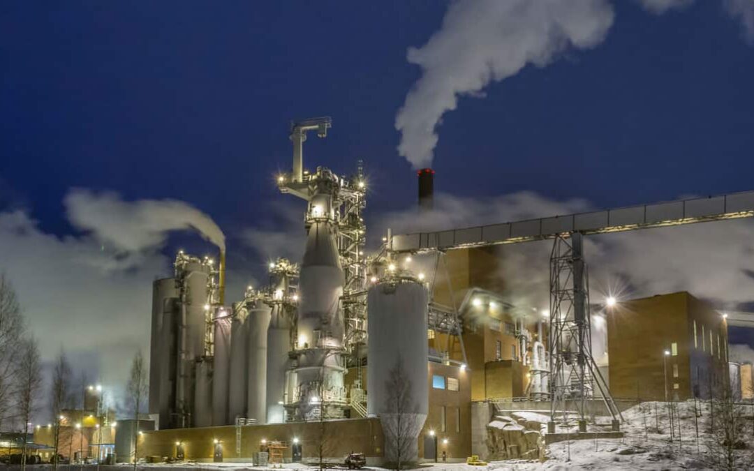
Wood pulping is the extraction of cellulose from wood, plant or a wide variety of other fibrous sources by dissolving the lignin that binds the cellulose fibers together. The 4 primary processes used in pulping are kraft, sulfite, neutral sulfite semi-chemical (NSSC), and soda. The selection of pulping process is largely determined by the end product, fibrous materials readily available, and economics. Kraft pulping is the most common form of chemical pulping, at 80% of the total chemical pulping industry.[1] This equates to nearly 130 million tons of kraft pulp generated annually. Most kraft pulping is performed in batch digesters, although as of recent years, continuous digesters have been installed more frequently. Wood chips, cooking liquor and steam are combined in a pressure vessel for each batch. The length of the cooking process depends on the desired yield and hardness of pulp but generally lasts 5-6 hours with temperatures maintained between 320 and 355°F. At the end of process, the pressure of the steam in digester pushes the cooked pulp out of the digester. The pulp proceeds through various stages of sorting, washing and other treatments before it is pressed and dried into finished products.
Batch Digester Materials of Construction
Batch digesters have historically been constructed of carbon steel with a thickness that includes a corrosion allowance to account for elevated erosion, corrosion mechanisms. In some cases a very thin 304 stainless steel cladding was applied at construction for nominal corrosion resistance. Batch cooking systems have changed over recent years seeking lower energy costs and liquor consumptions. Although deemed overall successful for site operations the more complex control systems have accelerated deterioration of the drums and other equipment making material selection more important than ever. When repairing or upgrading the alloy selections from construction many owners selected 309 stainless steel because of the chromium content known to be the most important alloying element in resisting corrosion attack by cooking liquors. Field 309 stainless steel overlay was frequently used for corrosion protection of both continuous and batch digesters made of carbon steel. More recently, an increasing number of batch digesters with 309 stainless steel overlays have been experiencing much higher corrosion rates making them less desirable and subject to replacement by superior alloying materials.
ER312ss Applied with WSI’s Patented Field Machine Welding Process
Due to the high chromium content in ER312 stainless steel filler materials, the weld overlay application was susceptible to weld solidification cracking when applied to a carbon steel substrate. WSI weld engineering developed a patented method to eliminate the weld solidification cracking as well as minimize the weld overlay’s thermal expansion mismatch with the base material. The weld deposit exhibits duplex microstructure which consists of both ferrite and austenite. The weld deposit solidifies as primary ferrite grains followed by precipitating austenitic grains. The resulting weld overlay with ER312ss achieves greater than 25% chromium in the overlay deposit and is considered to exceed the needs of most aggressively operated batch digesters corrosive environments. New digester vessels are often manufactured using duplex stainless steels similar to ER312ss alloy. The ER312ss weld overlay continues to be an efficient solution to significantly extend the life of these vessels and postpone replacement as well as a viable repairing alloy application to duplex lined vessels.
Machine Welding Approach to ER312ss or Other Duplex Stainless Steels
WSI is the world leader in pressure vessel life extension services. With the most extensive portfolio of life extension repairs, WSI can develop an ASME section VIII weld metal repair strategy with machine applied deposits to restore the wall to original thickness and extend the life of your asset with alloying materials. WSI’s proprietary GMAW machine welding process is ideal for ID applications, particularly digesters, because of the attractive economics proven versus other methods. Constructed by WSI engineers with sensor enabled parameter monitoring and digital control systems, the machine welding process has the ability to be easily field modified to handle any geometry and difficult welding position including conical sections of the digesters.
WSI
Whether the digester needs to be repaired emergently or during a planned turnaround, WSI has unparalleled innovative leadership in the pulp & paper, nuclear, refining, power generation and petrochemical industries. WSI has over 2000 ASME qualified procedures and over 1000 active welder certifications. Find out more about our engineered solutions and welding technologies at WSI.
[1] Nicholas P. Cheremisinoff, Paul E. Rosenfeld, in Handbook of Pollution Prevention and Cleaner Production, 2010
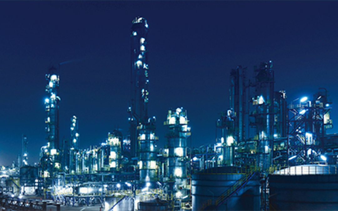
Hydrotreating technology is one of the most commonly used refinery processes, designed to remove contaminants such as sulfur, nitrogen, or metals
The hyrdotreater, sometimes referred to as the hydrodesulphurization or hydroprocessing unit, serve the purpose of removing sulfur compounds from hydrocarbons. By doing so, this piece of equipment can reduce sulfur dioxide (SO2) emissions as well as prevent poisoning of metal catalysts.[1] Prior to ultra‐low‐sulfur diesel (USLD) mandate, hydrotreating using elevated temperatures and moderate pressures through hydrogen catalyst reaction was used for straight run diesel. The National Petroleum Council (NPC) suggested that in order to produce diesel at less than 30 ppm sulfur, new high-pressure hydrotreaters would be required, operating at pressures between 1,100 and 1,200 psig.[2] Since that mandate, refiners have effectively had to desulfurize nearly all diesel blending components and undertake significant improvements in design, catalysts and other modifications to operations to produce ULSD. The units contain copious amounts of hydrogen gas, H2S, H2SO3 and other gases that can lead to a variety of challenges from hydrogen induced cracking (HIC), hydrogen induced disbonding (HID), hydrogen embrittlement, sulfide stress cracking and stress corrosion cracking. In condensing areas, other challenges such as general corrosion, pitting and hydrogen blistering can occur depending on the severity of the acids in the water.
High Temperature and High Pressure Hydrogen Service
ASME’s Boiler and Pressure Vessel Code Section VIII provides requirements for pressure vessels over PSIG 15 known as Division I. The modern hydrotreating processes addressing USLD mandates typically fall under ASME Section VIII Division 2 and its more rigorous requirements that oversee materials, design, fabrication and NDE. The industry uses this to demonstrate the adequacy of a pressure vessel in these types of severe service. In conjunction with ASME Code Section VIII Division 2 guidelines, API 934A applies to vessels that are designed, fabricated and certified for heavy wall pressure vessels for high temperature, high pressure hydrogen service. The recommended practices of API 934A cover a wide range of alloy materials including 2-¼Cr and 3Cr but also varieties of vanadium modified steels. Due to the severity of service in these reactors and the ranging failure mechanisms, API 934A recommends strict guidelines for materials selection, welding procedure qualification, and inspection.
Qualification process for API 934A recommendations
While not all refineries invoke API 934A for repairs to heavy wall reactors and division 2 vessels, those who do are seeking to reduce the risks of temper embrittlement over longer service periods. Qualification under this recommended practice is stringent and rigorous beginning with testing of each individual heat of welding consumables to be utilized. In order to simulate temper embrittlement, testing during the weld procedure qualification call for precise pre-heat, post weld heat treatment and controlled step cooling of the weldment. This is followed by comprehensive tensile, impact, bend, and hardness testing of multiple samples. The controlled heat treatment and extensive destructive testing both before and after step cooling validates that the qualified welding procedure will be resistant to temper embrittlement during subsequent service.
WSI’s internal weld engineering team successfully qualified the machine GTAW Hot-Pulse™ process exceeding the API 934A acceptance standards. Multiple welding processes were evaluated during the development of the repair procedures but only Hot-Pulse™ exceeded the rigorous testing requirements. For heavy wall reactor groove welding applications, WSI’s machine Hot-Pulse™ welding technology combines unparalleled deposition rates with superior weld puddle control. By utilizing a proprietary system of wire pre-heating, precise wire dabbing mechanics, and tightly controlled parameters the Hot-Pulse™ process eliminates porosity, improves weld grain refinement and is significantly less susceptible to fit up imperfections in field joints. This provides superior weld quality with increased production rates with reduced risk of failure.
WSI
Whether the reactor needs to be repaired emergently or during a planned turnaround, WSI has unparalleled innovative leadership in the refining, petrochemical, nuclear and power generation industries that exceeds API 934A standards. WSI has over 2000 ASME qualified procedures and over 1000 active welder certifications. Find out more about our engineered solutions and welding technologies at WSI.
[1] Zhu, F.(.X., Hoehn, R., Thakkar, V. and Yuh, E. (2016). Diesel Hydrotreating Process.
[2] National Petroleum Council, U.S. Petroleum Refining: Assuring the Adequacy of Cleaner Fuels
[3] Amiya Kumar Lahiri. Applied Metallurgy and Corrosion Control
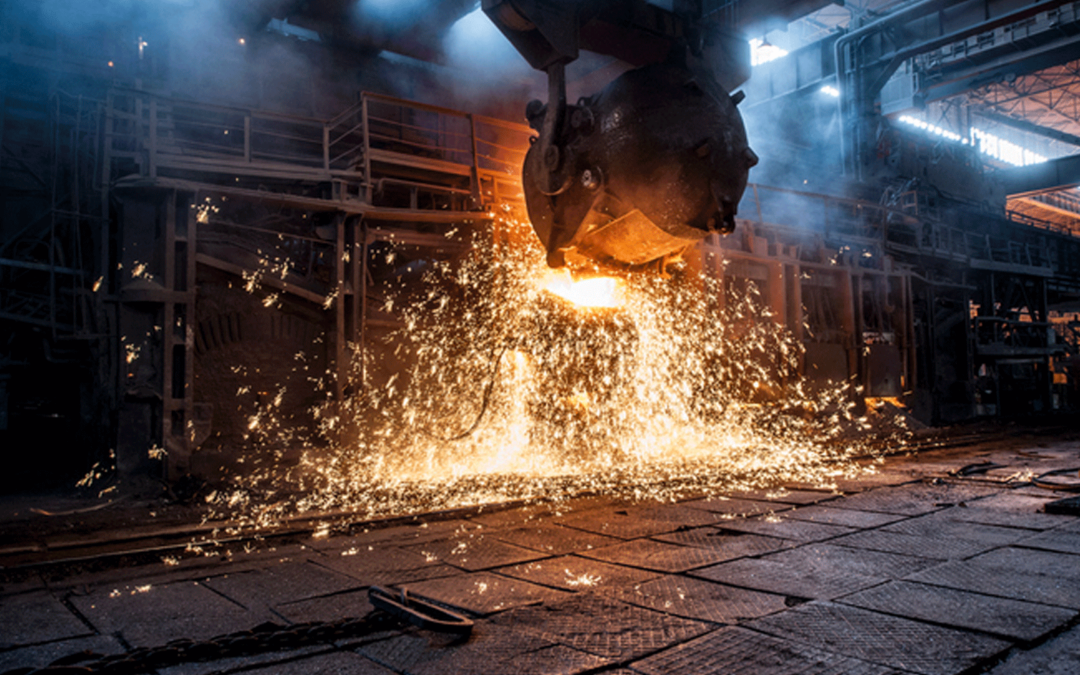
Electric Arc Furnace (EAF) technology prior to the 1970’s, mostly consisted of off-gas systems that were not water cooled but rather were designed with refractory lined steel plate. As the efficiency of the EAF process increased, water-cooled ducts were introduced because refractory lined ductwork was expensive to reline and the refractory linings were wearing away at accelerated rates. Water-cooled off-gas ductwork quickly became more economical than the refractory lined predecessor. Over time, EAF process loads continued to increase and even water-cooled plate ducts did not provide sufficient heat exchange. The next generation of EAF off-gas ductwork was of pipe (or tube) design water-cooled ducts, in current use today. Pipe construction water-cooled ducts are much more efficient at transferring the heat than the plate design systems because water flow rate is faster and more evenly distributed.
During the 1990’s, the advent of chemical energy packages with burner & lances came rapidly into common use. Chemical energy packages dramatically increased the efficiency of the EAF and reduced tap-to-tap times accordingly. The result, however, was a shortening of the life of water-cooled ducts. The life of water-cooled ducts, particularly those sections between the EAF roof and the drop-out box/combustion chamber went from being measured in years to months. The industry reached a point where the excess heat was at such a level that even carbon steel was no longer a suitable material for the water-cooled duct component construction. This presented a challenge because even increased flow rates were insufficient to create acceptable heat transfer and sufficient duct section cooling. Learn more about Unifuse Technology for EAF applications.
Operational Evaluations
The industry had come to a point in EAF process technology that to increase the life of water-cooled ductwork a significant change in heat transfer was required and improved materials were needed to allow operation at higher metal temperatures. To this effect, designers of water-cooled ductwork have experimented different materials from P22 pipe (aka Cr-Mo pipe), stainless steel pipe, aluminum bronze, spray-on refractory coatings and other types of coatings and spray cooling.
With the goal of operational reliability for a span of years, none of the applied methods had been able to make EAF off-gas water-cooled ductwork perform consistently or with the desired results. The owner’s evaluated many materials experiencing a wide variety of outcomes from high material cost with unacceptable return on investments, shorten life, to outright failure with the applications.
Failure Mechanisms
Thermal Fatigue Cracking occurs because the gas exposed side skin of the pipe wall or plate reaches a higher temperature than the cold side of the pipe. This temperature difference is cyclic because of the operating mode of the EAF thus resulting in low cycle thermal changes which eventually lead to fatigue cracking. Secondly, wall thinning occurs because the side of the waterwall that is exposed is exposed to high temperature corrosive gasses experiences oxidation. Because these surfaces are also exposed to medium to high velocity particulate flow, the oxidation layer is eroded by the particulate leaving new metal to re-form an oxide layer. These iron oxide layers are easily eroded because they are soft, and not very tenacious in their adherence to the base metal surface. Historically, in this industry, the answer to this problem has been to go with a thicker pipe to provide a corrosion allowance for this erosion-corrosion problem, but in most cases this simply leads to higher metal temperatures on the surface of the pipes which accelerates the erosion-corrosion mechanism. Lastly, in areas where the cool part of the operating cycle is sufficiently low, condensation of low melting point salts as well as water can be experienced. Accelerated erosion-corrosion wall thinning which may lead to initial failure due to loss of wall thickness can occur frequently in these areas. In some cases, the combination of water and contaminants from the process can create a highly corrosive environment which will result in pitting corrosion of the walls during non-operating windows. Condensation is typically experienced when the ambient air is warmer than the water being circulated through the duct. The sweating effect can also occur when the roof is swung off the furnace for charging, tapping or maintenance. During this time, the off-gas system is sucking in warm ambient air. The longer time it is allowed to suck in ambient air, the greater the propensity will be of creating this corrosive environment if the cooling water is at a lower temperature. Historically, the answer has been to install thicker pipe to combat the erosion-corrosion issue but in most cases this has led to higher metal temperatures on the surface of the pipes which accelerates the erosion-corrosion mechanism.
Successful Alternative for Duct and Hood Life Extension: Unifuse Technology for EAF Applications
Unifuse™ technology was patented by WSI resulting in a process for the fabrication of bimetallic tubes using a full fusion automated welded process. The welding parameters of the overlay are controlled through automation and designed to create an extremely low heat input during welding to minimize weld dilution and heat affected zone (HAZ) thickness. The resulting tubes are extremely ductile which allows the fabricator to execute bends necessary to achieve the final component configuration.
Unifuse™ 180 and Unifuse™ 360 for EAF Applications
With a focus on the primary failure mechanisms including wall thinning driven by erosion-corrosion, and thermal fatigue cracking caused by the cyclic operating process used in EAF plants, a successful mitigation is required for all. The unique makeup of the metallurgical composition of Alloy 625, coupled with WSI’s patented and proven weld metal overlay process provides a successful remedy for typical failure modes of EAF water-cooled ductwork and BOF water-cooled hoods. As a result, Unifuse Alloy 625 Weld Metal Overlay is changing the paradigm on how the industry will view Electric Arc Furnace water-cooled ducts and BOF water-cooled hoods by making them as permanent as other various components of the EAF, or BOF, whose life’s are measured in decades and not merely just a few years or even just months. These unusually long maintenance fee operational lifetimes make EAF water-cooled ducts and BOF water-cooled hoods fabricated from WSI’s patented Unifuse Alloy 625 Weld Metal Overlay process the lowest cost solution based on equipment replacement costs alone. Once one factors in the eliminated unscheduled down time due to premature failure or repairs, plus regained scheduled outage time to replace the carbon steel or aluminum bronze versions of the water-cooled ducts, the cost of ownership is reduced even further, making WSI’s Unifuse Alloy 625 Weld Metal Overlay process the lowest cost of ownership for an EAF water-cooled duct or BOF water-cooled hood.
WSI – The World Leader in Life Extension Solutions
Whether the furnace needs to be repaired emergently or during a planned outage, WSI has unparalleled innovative leadership backed by proven results in furnaces and boilers for longer than 40 years. WSI has the world’s largest portfolio of life extension projects and qualified procedures to handle unit specific challenges. Find out more about our various unit life extension solutions and engineered technologies at WSI.
[1] American Society of Mechanical Engineers, Boiler & Pressure Vessel Code, Section I, “Rules For Construction of Power Boilers”, ASME, New York, 2017.
Since 1975, global hydrogen demand has multiplied more than three times and continues to increase to date. Hydrogen is the most abundant element in the universe and generally contains environmentally benign properties. Considered a clean energy conversion, hydrogen can be easily transported, stored and blended with current fuels. Hydrogen produces no CO2 when combusted, only water and heat, making it versatile, environmentally friendly and extremely attractive to the global supply chain. Predating the internal combustion engine, hydrogen fuel cells powered the first designs over 200 years ago. According to the World Economic Forum, steam methane reforming (SMR) provides a significant amount of hydrogen produced globally.[1]
Steam Methane Reforming (SMR) is a technology commonly used to produce hydrogen in a refinery.
Approximately 95% of the hydrogen in the United States is generated via steam methane reforming, being utilized predominantly for petroleum refining and the production of industrial commodities such as ammonia.[2] SMR is considered a mature process of production in which methane reacts with 1200F – 1800F steam in the presence of a catalyst to produce hydrogen. The steam forming step, where methane reacts with water to produce carbon monoxide and hydrogen, is an endothermic process. Thus, the process is usually maintained at approximately 850°C to obtain optimal conversion.[3] The reformer furnace is where the process of releasing hydrogen from gas and steam begins. The furnace typically consists of a radiant section including the burners and a convection section to recover the waste heat of the flue gases leaving the radiant section. The gas burners apply heat to the mixture travelling in reformer tubes that hang vertically in rows generally constructed according to API-530. The reformer catalyst tubes perform under very rigorous conditions. The commonly used material essential to safe and reliable operation of this component is an alloy 800 variant such as Incoloy 800 HT. Although these materials provide effective failure protection in the environment, the welding of these materials have a significant effect on performance. The high temperature cycling during operation make these tubes susceptible to cracking at the welds.
Avoiding costly, time consuming catalyst tube replacements
Catalyst tube banks typically terminate at the top and bottom of the furnace leaving only inches of clearance at the flange. The tubes may experience obstructions from the foundation at the bottom of the furnace, catwalks, ducting, refractory, roofing, and hangers. In other cases the catalyst tube designs have pigtail tubes near the flange connections. All of these interferences create a situation in which making a welded connection is extremely difficult using conventional methods forcing owners to replace the entire catalyst tube during turnaround. With the primary challenges being limited axial and radial clearances to make the OD flange weld, WSI has designed both an engineered ID solution with cutting and welding as well as a low profile OD welding approach. Both configurations have the ability to be remotely operated and utilizes Gas Tungsten Arc Welding to achieve first time x-ray quality from the completed joint. WSI maintains a variety of engineered repair solutions that can be approached from the ID or OD in order to condense schedule, eliminate manpower in congested work areas and achieve first time quality.
WSI
Whether the reformer furnace needs to be repaired emergently or during a planned turnaround, WSI has unparalleled innovative leadership in the nuclear, refining, power generation and petrochemical industries. WSI has over 2000 ASME qualified procedures and over 1000 active welder certifications. Find out more about our engineered solutions and welding technologies at WSI.
One of the largest problems for the refining, chemical and petrochemical industry
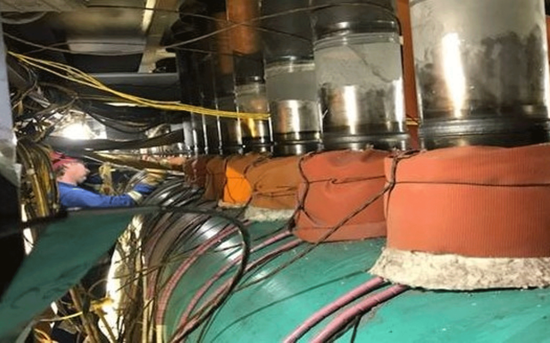
Corrosion under insulation (CUI) is a common issue across many industries including refining and chemical processing. According to a study presented by ExxonMobil, the highest incidence of leaks in the refining and chemical industries are due to CUI and not process corrosion.[1] CUI is concealed from view and can remain unobserved until the insulation system is removed for inspection. Visible signs of corrosion can cascade from the jacketing or when leaks appear. CUI can be defined as localized external corrosion occurring in insulated equipment fabricated from carbon and low-carbon steels. The operating temperature of the pressure vessel is extremely important as above 350°F low carbon steels will evaporate water from the surface and under 25°F corrosion rates are dramatically reduced. CUI occurs beneath insulation and jacketing as a result of water penetration into the insulating system. Water entering the insulating system can materialize with rainfall, steam, condensation and a variety of other areas. Once water enters into the insulating system, contaminants such as salts, can be introduced as an accelerant the corrosion to the exterior of the pressure vessel. Learn about WSI’s machine welding approach to CUI restoration.
The inevitable failure of insulation systems in vertical pressure vessels
The insulating system is made up of several key elements to help slow the corrosive process. A coating, considered the last line of defense, is first applied to the exterior base material. Next, the insulation is applied to buffer sound, conserve heat and other energy from the vessel as well as serve as further protection in some cases. Lastly, a jacketing is banded to the exterior of the system to protect insulation from the elements and other mechanical damage. The materials for these systems can vary greatly and fail with as much frequency. Mechanical damage is only one of the failure modes that allows water to enter the system. Design, maintenance and initial installation can also contribute to failure of the system. Due to the failure modes, vertical pressure vessels tend to experience similarities in locations that CUI occurs. Typically vertical pressure vessels experience CUI at locations such as welded clips, insulation rings and stiffener support rings as well as top head center nozzles.
Engineering analysis to identify fatigue, mitigate risk and optimize availability
In order to determine what available options can be considered for CUI repair, the extent of the corrosion damage has to be properly assessed. Once the damage has been characterized, an engineered repair approach can be implemented to determine the optimal solution for the facility. Consideration should be paid to the area, depth, locations of the corrosion, equipment operating conditions, insulating system, failure mode and life expectancy. A fitness-for-service (FFS) assessment can predict the expected life of various repair scenarios, helping to determine the best solution. For extensive repairs, a predictive distortion analysis can be applied to optimize the repair to minimize distortion and ovality. In many cases, a machine welded repair by weld metal buildup is much more schedule efficient and cost effective than section replacement.
Machine Welding Approach to CUI Restoration
WSI can develop an ASME section VIII weld metal buildup (WMBU) repair strategy with machine applied deposits to restore the wall to original thickness in lieu of plate replacements and window cut outs in the vessel. WSI’s proprietary GMAW machine welding process is ideal for OD applications particularly CUI because of the custom automatic proportional height control. This feature allows for our machines to electronically measure the tip to work distance over 200 times a second in order to ensure uniform deposition thickness and optimum dilution rates. Furthermore, the weld nozzle has a stroke capability of 9” in order to address a variety of corrosion depths experienced during repair applications. Constructed by WSI engineers with sensor enabled parameter monitoring and digital control systems, the machine welding process has the ability to be easily field modified to handle any geometry and difficult welding position.
WSI
Whether the pressure vessel needs to be repaired emergently or during a planned turnaround, WSI has unparalleled innovative leadership in the nuclear, refining, power generation and petrochemical industries. WSI has over 2000 ASME qualified procedures and over 1000 active welder certifications. Find out more about our engineered solutions and welding technologies at WSI.
[1] A.A. Mokhtar, et al. Engineering Management Asset Systems
OD Weld Metal Buildup Applied with WSI Machine GMAW for CUI